You have a resonant tank circuit. You have a power supply of an unknown frequency.
I am failing to see what you are after other than to feed an unknown frequency into a resonant tank which will end up with a crude heterodyne.
You need to explain a bit better.
Mikado
The Quonset Hut
Discussions of Townsend Brown and other Obscure Scientists, their work, lives and everything else in the Universe.
the power source to experiment with technology Gravitor
39 posts
• Page 3 of 4 • 1, 2, 3, 4
Re: the power source to experiment with technology Gravitor
![]() by Mikado14 » Fri Mar 18, 2016 11:18 am
by Mikado14 » Fri Mar 18, 2016 11:18 am
The thing about Inner Circles is that they are like Boxes - difficult to think outside of them.
"When the Debate is Lost, Slander is the Tool of the Loser" SOCRATES
“There are two ways to be fooled. One is to believe what isn't true; the other is to refuse to believe what is true.”
― Søren Kierkegaard
"When the Debate is Lost, Slander is the Tool of the Loser" SOCRATES
“There are two ways to be fooled. One is to believe what isn't true; the other is to refuse to believe what is true.”
― Søren Kierkegaard
-

Mikado14 - Commander
- Posts: 2054
- Joined: Sat Jul 09, 2011 10:38 am
- Location: Located where I want to be...or not...depends on the day.
Re: the power source to experiment with technology Gravitor
![]() by Antigravitic » Fri Mar 18, 2016 1:12 pm
by Antigravitic » Fri Mar 18, 2016 1:12 pm
Mikado14 wrote:You have a resonant tank circuit. You have a power supply of an unknown frequency.
I am failing to see what you are after other than to feed an unknown frequency into a resonant tank which will end up with a crude heterodyne.
You need to explain a bit better.
Mikado
truth is an RLC resonant tank, the spark gap generates an energetic shove and oscillated, is like hitting a bell, the hammer gives equal the resonance frequency of the bell, the mission of the hammer is only hit hard and download mechanical energy in a very short time.
"...one must first understand the nature, then imitate..."
-

Antigravitic - Petty Officer 2nd Class
- Posts: 94
- Joined: Sat Mar 12, 2016 5:14 pm
- Location: sagunto (valencia) Spain
Re: the power source to experiment with technology Gravitor
![]() by Mikado14 » Fri Mar 18, 2016 2:36 pm
by Mikado14 » Fri Mar 18, 2016 2:36 pm
No. It is not an RLC tank. It is an RC parallel tank, there is no L. You do not need a High Frequency component to your HV power Supply. You can control the discharge rate of the spark gap to discharge the tank and thus it will build back up. You adjust the gap of the spark gap to arc somewhere on the 4th time constant of the tank. Each time constant is 63.2 percent of the remaining charge.
So, at the fourth time constant it will be lower than the peak value of your supply and discharge to a certain amount (unknown at the moment for I don't feel like doing the calculations) and the cycle will repeat.
Where does the hammer come into play?
Mikado
PS: the value of the fourth time constant needs to be lower than the simple Ohm's law calculation for the parallel resistor....and it will still need an R in series with the RC tank. You need a voltage divider to make it work.
The thing about Inner Circles is that they are like Boxes - difficult to think outside of them.
"When the Debate is Lost, Slander is the Tool of the Loser" SOCRATES
“There are two ways to be fooled. One is to believe what isn't true; the other is to refuse to believe what is true.”
― Søren Kierkegaard
"When the Debate is Lost, Slander is the Tool of the Loser" SOCRATES
“There are two ways to be fooled. One is to believe what isn't true; the other is to refuse to believe what is true.”
― Søren Kierkegaard
-
Mikado14 - Commander
- Posts: 2054
- Joined: Sat Jul 09, 2011 10:38 am
- Location: Located where I want to be...or not...depends on the day.
Re: the power source to experiment with technology Gravitor
![]() by Antigravitic » Sun Apr 03, 2016 6:25 pm
by Antigravitic » Sun Apr 03, 2016 6:25 pm
Hola Amigos, estoy trabajando en mi nueva fuente de alta tensión, espero conseguir 300Kv-200uA, la tension de ruptura del aire seco son aproximadamente 3Kv/m.m...............................Hello Friends, I'm working on my new high voltage source, hope to get 300kV-200uA, the breakdown voltage of dry air are approximately 3 kV / m.m
https://youtu.be/XAdWoKKkIrk

https://youtu.be/XAdWoKKkIrk
"...one must first understand the nature, then imitate..."
-
Antigravitic - Petty Officer 2nd Class
- Posts: 94
- Joined: Sat Mar 12, 2016 5:14 pm
- Location: sagunto (valencia) Spain
Re: the power source to experiment with technology Gravitor
![]() by kevin » Mon Apr 04, 2016 3:26 am
by kevin » Mon Apr 04, 2016 3:26 am
- kevin
- The Hobbit
- Posts: 2901
- Joined: Tue May 05, 2009 1:24 pm
Re: the power source to experiment with technology Gravitor
![]() by Antigravitic » Mon Apr 04, 2016 5:31 am
by Antigravitic » Mon Apr 04, 2016 5:31 am
"...one must first understand the nature, then imitate..."
-
Antigravitic - Petty Officer 2nd Class
- Posts: 94
- Joined: Sat Mar 12, 2016 5:14 pm
- Location: sagunto (valencia) Spain
Re: the power source to experiment with technology Gravitor
![]() by Antigravitic » Mon Apr 04, 2016 11:56 am
by Antigravitic » Mon Apr 04, 2016 11:56 am
with this voltage multiplier I hope to raise the pressure up to 150 kV DC, I have ordered 2 analog voltmeters 100kV and two Microammeters, I hope to have the fountain built in a week.
"...one must first understand the nature, then imitate..."
-
Antigravitic - Petty Officer 2nd Class
- Posts: 94
- Joined: Sat Mar 12, 2016 5:14 pm
- Location: sagunto (valencia) Spain
Re: the power source to experiment with technology Gravitor
![]() by Mikado14 » Mon Apr 04, 2016 12:16 pm
by Mikado14 » Mon Apr 04, 2016 12:16 pm
Antigravitic wrote:with this voltage multiplier I hope to raise the pressure up to 150 kV DC, I have ordered 2 analog voltmeters 100kV and two Microammeters, I hope to have the fountain built in a week.
You may discover that 200uA may be a bit on the low side. We had a supply that was capable of 600uA but it eventually died. To much inrush current.
Be sure that you insert a load resistor in series with your capacitor/gravitor. This will balance the load on inrush so that the supply doesn't have it's current capacity exceeded.
Mikado
The thing about Inner Circles is that they are like Boxes - difficult to think outside of them.
"When the Debate is Lost, Slander is the Tool of the Loser" SOCRATES
“There are two ways to be fooled. One is to believe what isn't true; the other is to refuse to believe what is true.”
― Søren Kierkegaard
"When the Debate is Lost, Slander is the Tool of the Loser" SOCRATES
“There are two ways to be fooled. One is to believe what isn't true; the other is to refuse to believe what is true.”
― Søren Kierkegaard
-
Mikado14 - Commander
- Posts: 2054
- Joined: Sat Jul 09, 2011 10:38 am
- Location: Located where I want to be...or not...depends on the day.
Re: the power source to experiment with technology Gravitor
![]() by Antigravitic » Tue Apr 05, 2016 9:46 pm
by Antigravitic » Tue Apr 05, 2016 9:46 pm
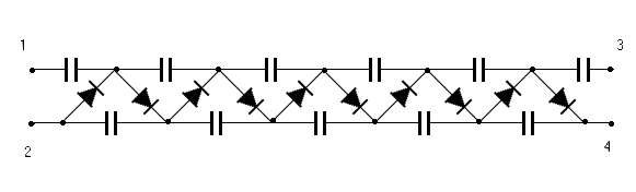
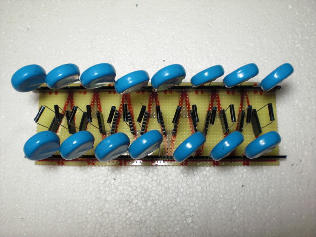
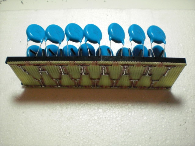
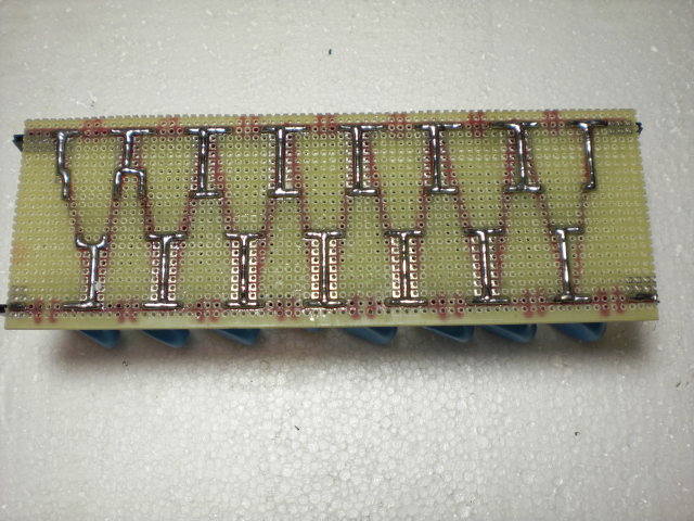
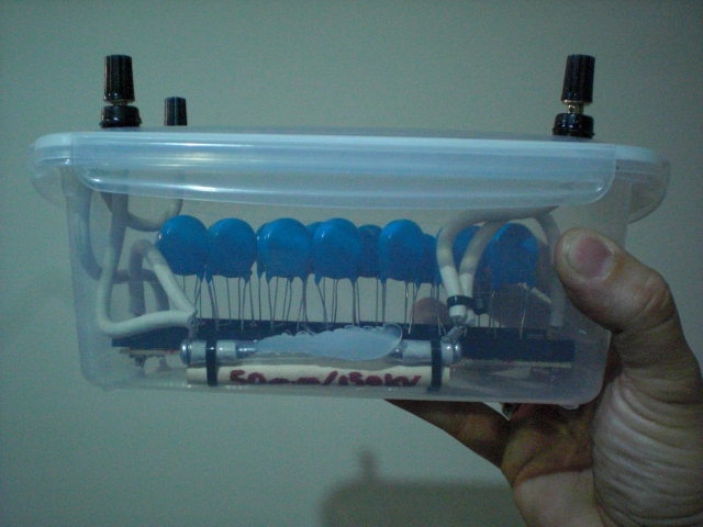
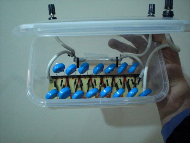
Este es mi segundo multiplicador de tensión de 7 etapas acabado, la gran diferencia con el primero es que todos los diodos y condensadores pueden ser reemplazados en un periquete, me he fabricado un comprobador para tal efecto, y las distancias de los bornes en la caja son mayores pues en el primer modelo llegaron a saltar chispas de 120m.m de borne a borne (sobre 360Kv a razón de 3Kv/m.m aire seco) aparte en este he implementado un sistema de seguridad para no romper los condensadores al someterlos a una tensión superior a la máxima admisible que consiste en un boquete de chispa con 50 m.m de separación (en principio)............................................
This is my second voltage multiplier 7 finishing stages, the big difference with the first is that all diodes and capacitors can be replaced in a jiffy, I've made tester for this purpose, and distances of the terminals in the box they are greater because in the first model came to sparks of 120m.m from terminal to terminal (on 360Kv at a rate of 3 kV / mm dry air) apart on this I have implemented a security system to avoid breaking the capacitors when subjected to a voltage higher than the maximum permissible consisting of a spark gap with 50 mm apart (in principle)
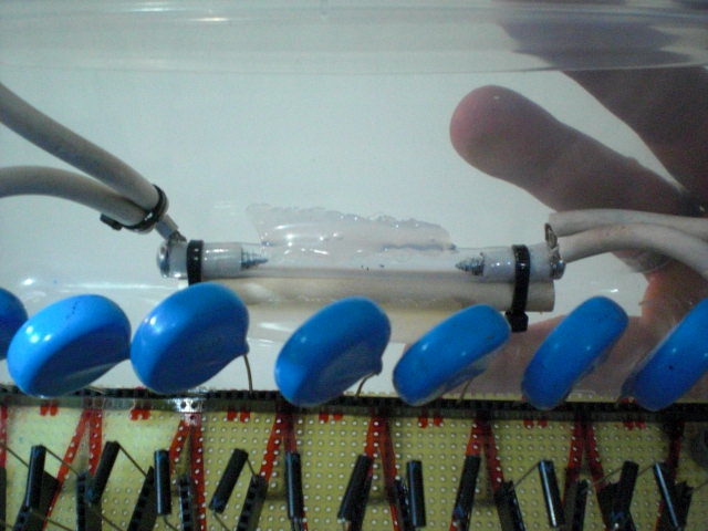
Detalle del boquete de chispa calibrado a 50m.m de separación (+-150Kv a razón de 3Kv/mm)...............................Detail calibrated spark gap 50 m.m separation (+ -150Kv at a rate of 3 kV / mm)
http://electricidad.usal.es/Principal/C ... p?b=id:154
This is my second voltage multiplier 7 finishing stages, the big difference with the first is that all diodes and capacitors can be replaced in a jiffy, I've made tester for this purpose, and distances of the terminals in the box they are greater because in the first model came to sparks of 120m.m from terminal to terminal (on 360Kv at a rate of 3 kV / mm dry air) apart on this I have implemented a security system to avoid breaking the capacitors when subjected to a voltage higher than the maximum permissible consisting of a spark gap with 50 mm apart (in principle)
Detalle del boquete de chispa calibrado a 50m.m de separación (+-150Kv a razón de 3Kv/mm)...............................Detail calibrated spark gap 50 m.m separation (+ -150Kv at a rate of 3 kV / mm)
http://electricidad.usal.es/Principal/C ... p?b=id:154
"...one must first understand the nature, then imitate..."
-
Antigravitic - Petty Officer 2nd Class
- Posts: 94
- Joined: Sat Mar 12, 2016 5:14 pm
- Location: sagunto (valencia) Spain
Re: the power source to experiment with technology Gravitor
![]() by Antigravitic » Tue Apr 05, 2016 9:49 pm
by Antigravitic » Tue Apr 05, 2016 9:49 pm
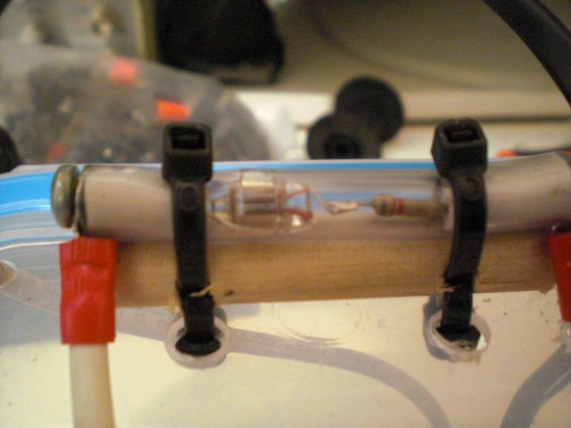
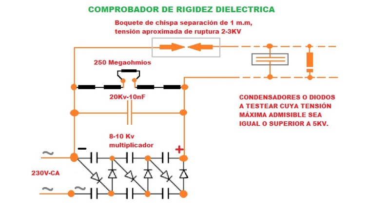
Hola Amigos, he perfeccionado un poco mas el sistema, he incorporado un tubito de neón y una resistencia de 8k en serie, de esta forma se mejora la sensibilidad a la hora de apreciar las hipoteticas fugas de los elementos a testear....................................................................................Hello Friends, I have improved a little but the system has incorporated a neon tube and 8k resistor in series, thus sensitivity when assessing the hypothetical leakage of the elements to be tested is improved.
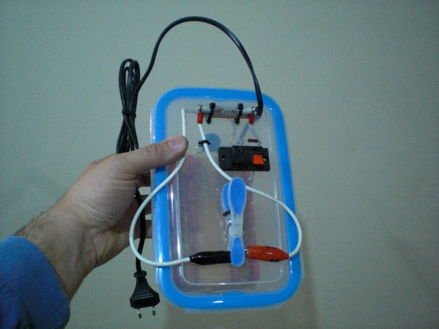
Aquí os dejo un video donde se pone de manifiesto el simple funcionamiento del aparato y donde testeo 2 condensadores, uno de ellos presenta fugas a alta tensión y el otro está nuevecito de trinqui y aparentemente no presenta fugas observables en el detector de neón (que no quiere decir que no las haya, tan solo que son tan despreciables que no se detectan por este método).....................................................................................
Here I leave a video where shows the simple operation of the device and where testing 2 capacitors, one of them leaks at high pressure and the other is brand new from Ratchet and apparently no observable leakage detector neon (not means that there are none, just that they are so despicable that are not detected by this method)
https://youtu.be/FOPieJ7wYks
Tan solo me queda para rematar la faena incorporarle un voltimetro de 20.000Voltios, de esa forma sabré mediante pruebas destructivas la tensión máxima que aguantan algunos dielectricos, condensadores artesanales o convencionales y diodos polarizados inversamente, tan solo con variar la tensión del auto-transformador (variac) puedo hacer ensayos no destructivos o destructivos jajajaja.....................................................................So I just have to finish the job 20.000Voltios incorporate a voltmeter, thus know by destructive testing withstand the maximum voltage that some dielectrics, craft or conventional capacitors and diodes reverse biased, just by varying the voltage auto-transformer ( variac) I can do non-destructive or destructive testing hahaha
https://youtu.be/dyR91KTNNeA
En principio use un boquete de chispa como "testigo" de carga, ahora lo he perfeccionado empleando un bulbo de neon y una resistencia de 10k en serie.........................In principle use a spark gap as a "witness" charge, now I've perfected using a neon bulb and a 10k resistor in series.
"...one must first understand the nature, then imitate..."
-
Antigravitic - Petty Officer 2nd Class
- Posts: 94
- Joined: Sat Mar 12, 2016 5:14 pm
- Location: sagunto (valencia) Spain
39 posts
• Page 3 of 4 • 1, 2, 3, 4
Who is online
Users browsing this forum: No registered users and 3 guests